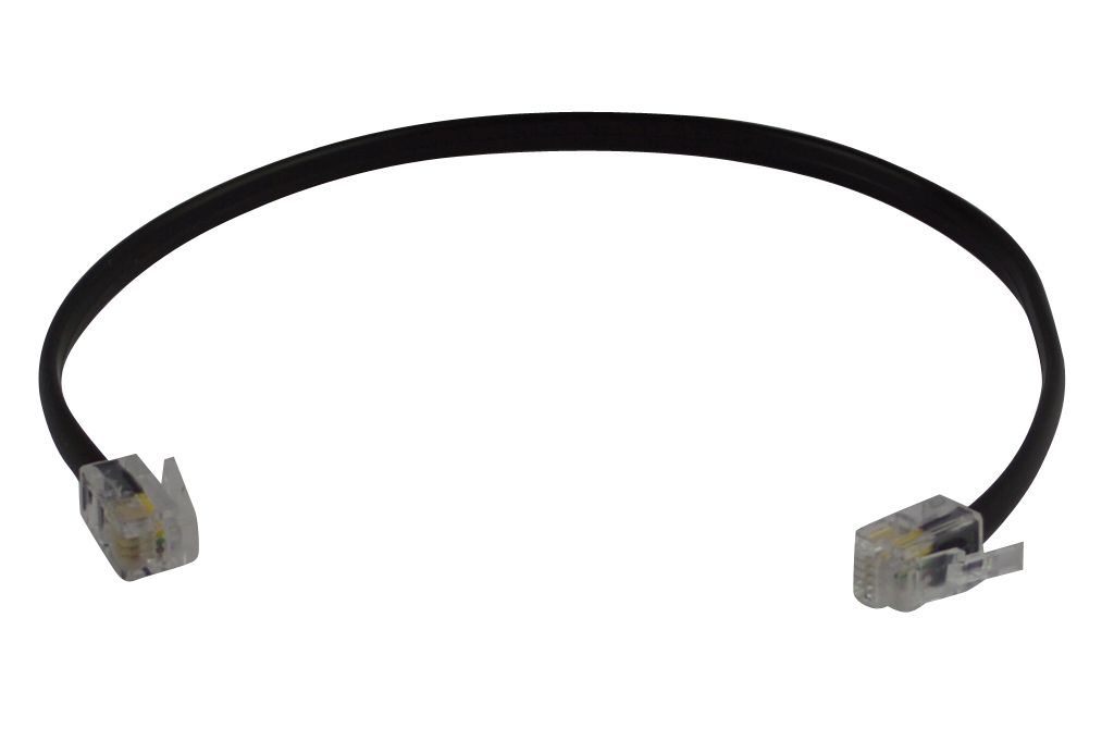
Boost Your Rs485 Cable With These Tips
페이지 정보
작성자 Matthew Castano… 작성일 24-07-17 18:44 조회 4 댓글 0본문
Having a second serial port is also handy for system debugging. The Serial ports are implemented by the dual on-chip hardware UARTs (Universal Asynchronous Receiver/Transmitters) on the Freescale 9S12 (HCS12) microcontroller. RS232 uses inverse logic; that is, a positive bit at the HCS12 UART is inverted by the onboard RS232 driver chip and appears as a negative signal on the serial cable. We can gain insight into the operation of the RS232 protocol by examining the signal connections used for the primary serial port in the above table. Enabling RS485 on the Serial2 port is parallel to the process described above. 5 should work in your situation because of the voltage you will be running (5-10V) and your signal is not high frequency (above 500Mhz) in the first place. Chassis and signal grounds are connected together to the digital ground (DGND) signal. From the PDQ Board’s point of view, these three signals (/TxD, /RxD, and ground) are the only connections required to perform serial communications. Of the processor’s three synchronous SPI (Serial Peripheral Interface) ports, two are available for inter-processor communications on multi-processor systems, and the third is brought out to the Wildcard expansion bus. Two asynchronous communications ports named Serial1 and Serial2 can each be configured for RS232 or RS485 protocols.

The Serial 1 and Serial2 ports can be configured for either RS-232 or RS-485 communications at standard baud rates up to 115200 bits per second. The EIA has officially disbanded and the standard is now maintained by the TIA as TIA-485, but engineers and applications guides continue to use the RS-485 designation. This page describes the serial ports and how to use them for instrument control and automation applications. After a factory cleanup, Serial1 is the default serial port for program development and downloading. The default baud rate after a factory cleanup is 115200 baud. In general, all devices on a network should use the same phase, polarity, and baud rate clock signal. The RS232 protocol specifies the use of two separate grounds, a signal ground and a protective (or chassis) ground. The shield works as a "drain" for any noise that could be picked up by the RS485 network and "drain" it to ground. Gepco a Belden Brand, Flexible DMX512 Lighting Control Cable, 4 Conductor 24 AWG (7x32) stranded tinned copper, Foam PE insulation, foil shield plus 90% TC braid with 24 AWG stranded TC drain wire, all weather TPE jacket. To provide a convenient means of attaching two grounds to the serial cable, there are several pins (labeled DGND) on the communications connector that are connected to the controller’s ground plane.
Although the RS232 protocol specifies functions for as many as 25 pins, each communications channel requires only three for simple serial interfaces: /TxD1 (transmit data), /RxD1 (receive data), and DGND (digital ground). Most computers conform to IBM PC AT-compatible RS232 interfaces which use 9-pin D-Type connectors, consequently the PDQ Board brings out its serial ports to two female 9-pin D-Type connectors on the Docking Panel. The primary and secondary serial communications ports are accessible through the PDQ Board's 10 pin, dual row Communications Header (H2) and through the Docking Panel's 10 pin, right-angle, dual row Communications Header (H1) and individual DB-9 Serial 1 and Serial 2 connectors. A level converter chip like MAX232 is needed to convert voltage levels between serial ports and microcontrollers. Using the FT232R chip combined with an RS485 level converter, the cable is CE, FCC and UKCA approved product which is one of the simplest USB - RS485 solutions around. The diagram below shows potentials of the A (blue) and B (red) pins of an RS-485 line during transmission of one byte (0xD3, least significant bit first) of data using an asynchronous start-stop method. So, for eight data bits with a parity bit, M would be set (equal to one) in order to add an extra bit to each byte transmitted, and PE would be set in order to make that extra bit be used as a parity bit.
If a slave device has already stored a byte into its SPDR register, that byte will be exchanged with the master’s byte. Another major advantage is that there can be more than one slave in the connection. Setting the MSTR bit initializes the QScreen as a master, and clearing the MSTR bit initializes it as a slave. The data bits are also transmitted in reverse order, with the least significant bit transmitted first, after a start bit. Each serial port can be configured for the RS232 or RS485 protocol, and runs at standard baud rates up to 115,200 bits per second. These 9-pin standard DB-9 serial connectors are located on the back of the Docking Panel. The following table shows the connection diagram for a standard 9-pin serial cable. All of the RS232 signals start with the / (slash, pronounced not) character to indicate that the signals on the serial cable are logically inverted. Two RS485 transceivers are present on the PDQ Board, one for each channel.
If you are you looking for more info on rs485 cable look into the site.
- 이전글 Five Recommendations on 宜蘭外燴 You Cannot Afford To overlook
- 다음글 The Fundamentals Of 整骨學徒 Revealed
댓글목록 0
등록된 댓글이 없습니다.

